We suggest here mainly as modern experiment based on the experiments and findings of Tesla, that of professor Konstantin Meyl
1) MINIATURE TESLA TOWERS TO MEASURE "FREE-ENERGY" of the electromagnetic SCALAR WAVES.
3) As a 3rd example of Tesla-like experiments, we might like to investigate the findings of Kapanatze, that are not irrelevant to the experiments of Tesla.
B) The next set of instructions is taken mainly from the experimental work of the laboratory of Jean Louis Naudin. (http://jnaudin.free.fr/kapagen/index.htm) and in particular version 3.2 and 3.3.
The suggested design and construction below is quite different I think from the original design in the patent of T. Kapanadze which can be found here
http://v3.espacenet.com/publicationDetails/originalDocument?CC=WO&NR=2008103130A1&KC=A1&FT=D&date=20080828&DB=EPODOC&locale=en_EP
In all videos that I am aware that have successfully realized a Kapagen-like device, where they get more power as output than as input, do utilize three coils in the cylinder configuration of coils and not only two. The circuit connections of the last video above, are claimed by the amateur that are the only that make it work, and not have the coils cancel out the their effects.
The circuit of this last amateur is shown also here
http://img600.imageshack.us/img600/1791/imageknr.jpg

All informations and diagrams are published freely (freeware) and are intended for a private use and a non commercial use.

The main circuit
Here is the diagram of the main circuit.

This main cicuit is creating a pulsating electric current because of the spark gap, the capacitor, the resistance, the diode and the induced current from the input power trasnformer (not seen in this part of the circuit).


The spark gap
In the version v3.2 the spak gap was from two rods of tungsten. ( air gap 0.9 mm)


The Grounding


The input power
1) MINIATURE TESLA TOWERS TO MEASURE "FREE-ENERGY" of the electromagnetic SCALAR WAVES.
In the link below, professor Konstantin Meyl describes in detail simple experimental setting of miniature Tesla towers in University laboratory, so as to measure beyond doubt the free-energy. He also proves the existence of scalar (non-vector or non-Herz) ) waves of the electromagnetised aether (I assume them to be scalar waves of the scalar electromagnetic potential) . In neutral aether, such waves would be the aether sound compression waves (travelling of course at the speed around that of light, or in cases that molecular mater is present maybe faster than light).
This professor has published papers, and books about his findings, and has developped his own unified-field theory. And what is also practical, he has designed and sells, experimental kits (for about 300 euros) of miniatures of the Tesla-towers, where he measures in the receiver tower 4 times more power (in milli-volts), as "free energy".
Hos publications and kit can be found in the above link.
2) The Quantum Energy Generator (QEG) is an open source project to construct and install a free-energy generator. It is an adoption of an old 1894 patent by Tesla, for an electric generator.
The blue prints
parts and tools
3) As a 3rd example of Tesla-like experiments, we might like to investigate the findings of Kapanatze, that are not irrelevant to the experiments of Tesla.
B) The next set of instructions is taken mainly from the experimental work of the laboratory of Jean Louis Naudin. (http://jnaudin.free.fr/kapagen/index.htm) and in particular version 3.2 and 3.3.
The suggested design and construction below is quite different I think from the original design in the patent of T. Kapanadze which can be found here
http://v3.espacenet.com/publicationDetails/originalDocument?CC=WO&NR=2008103130A1&KC=A1&FT=D&date=20080828&DB=EPODOC&locale=en_EP
We must notice in advance, that the present realization v3.3 of the Kapanadze device, by Jean Louis Naudin, is so that the device fails , in the sense, that it does not give more power, that the given input power. But this is not what Kapanadze did. I only give the details of v3.3 realization by J.L. Naudin, because I know of no other very detailed data of realization that did succeed (except perhaps the next video by Andre Fabrice , http://www.youtube.com/watch?v=B6hVasVR7AI and more material here http://pesn.com/2013/04/13/9602295_Demos_by_Fabrice-Andre_Refuge7/ ) . Nevertheless, as J.L. Naudin has published in the same page, of his site, some of the experimenters claim that they did get more output power than the input power. E.g. the exprimenter Robert below, ( # 10 - June 21, 2010), did succeed, to have more power at the output (1800W) relative to the input power (800W). But this only after persisting experimentation, after changing the diode with another, and his coil too has three parts of different number of turns (22-84-6) that the current version v3.3. It seems also that the experimenter Romerouk (# 3 - June 10, 2010 - Kapagen replication v1.1 and 1.2 ) did succeed to have more output power that input power.
Another important remark is that the instructions of J.L. Naudin , in his site do not specify explicitly the clockwise or counterclockwise winding of the three or two parts of the coils, and the placing of them on the tube. But even if he did we know that he failed to get more power as output than as input. The next video is from an amateur who does carefully specifies, the directions of the turns of the three coils and gives also a slightly different circuit diagram.
http://www.youtube.com/watch?v=hQVfW1yUqTo
In all videos that I am aware that have successfully realized a Kapagen-like device, where they get more power as output than as input, do utilize three coils in the cylinder configuration of coils and not only two. The circuit connections of the last video above, are claimed by the amateur that are the only that make it work, and not have the coils cancel out the their effects.
The circuit of this last amateur is shown also here
http://img600.imageshack.us/img600/1791/imageknr.jpg

We may notice that according to the orientations clockwise/counterclockwise on the geometry of the three coils, and after the circuit connections that the previous amateur proposes with a grounding connected in between the three coils, it seems as if he is having the next configuration: a transformer, that in its primary part (coils 22 turns/84 turns) it is given a high voltage non-DC current, and so that the secondary part (coil 6 or 9 turns) gives the output current with extra energy, and both primary and secondary have a common pole in the grounding. The above configuration is so that there are two non-equal magnetic fields from the coils with opposite (repelling) position of their north and south poles. Such a configuration of magnetic fields is almost identical the the magnetic fields of the two wheels of the old overunity device of testatika (in the community of Methernitha). (See post 1)
So my suggestion is , to start with the details of J.L. Naudin that we know that he failed, utilize three coils and not two coils and then experiment with different circuit connections as the above amateur.
The Kapagen-related method by Andre Fabrice as in
deviates much more that the details of J.L. Naudin.
All informations and diagrams are published freely (freeware) and are intended for a private use and a non commercial use.
Warning!
Due to the presence of High Voltage and the High Power output of the Kapagen, users of this document should be very carefull and experienced in High-Voltage electronics to try anything out ! If you do it, the risk of any result is just yours. I take no responsibility of anything that might happen.
Testing such a device needs a lot of caution and the use of safety procedures, the experimenter must be very skilled in the use of High Voltage at High Power...
The main circuit
The double coil
The diode HV 05-12 F04 (Later constructors have experimented with different diodes, so that the diode remains cool)
The spark gap ( air gap 0.9 mm) (Both rods of the spark gap from tungsten. Later constructors have put the one rod of the spark gap from copper and the other from carbon, which makes the spark gap silent during discharges, and reduces input power by 55 watts)
The capacitor HV 1μF 2000V AC
The resistance 10 M Ohms Internal (1 W )
In the above circuit circulates about 2000 Volts AC.
Here is the diagram of the main circuit.

This main cicuit is creating a pulsating electric current because of the spark gap, the capacitor, the resistance, the diode and the induced current from the input power trasnformer (not seen in this part of the circuit).
The beneficial energy job is done from the double coil that you see in the diagram. It is not a transformer, and to many may seem like a grounded antenna.
Some conjectural theory:
What it does, according to my understanding is to create an asymmetric (conical) twistor in the electromagnetic field or electromagnetised aether (=charged and in motion aether) which subtracts heat energy from aether and converts it to kinetic, in other words electric current. Or maybe tow opposite twisters if it is utilized two or three coils and according to their placement and clockwise or counterclockwise orientation of the turns of the coil. This is similar to the air-twisters (tornados) that as the air is moving in their conical section, is expanding, the temperature drops, air-heat is converted to kinetic energy and the twister motion is preserved. In aether the aether temperature is proportional to the scalar gravitational potential φ, and thus we may say that the energy is extracted from the potential energy of the gravitational field. Of course according to our standard knowledge of the gravitational field this seems impossible, but on the other hand it seems that we know only 4/10 or 6/10 of what fully is the gravitational field. See e.g.
http://thenewuniversalattraction.blogspot.gr/
or
http://users.softlab.ece.ntua.gr/~kyritsis/PapersinPhysics/Lancast8_suspended.pdf
The double coil
How the double coil is made:
A PVC tube (Cylinder) for the coils, of diameter 5 cm , length 32 cm
2 sockets at the two circular ends of the tube to connect the wires from the rest of the circuit.
The tube has a long coil on its surface of 108 turns, that occupies about 23 cm length of the tube. The wire for this coil is not more than 30 m, 1.5 square mm (mm^2) cross-section, insulated.
It has also a short coil of only 6 turns, of 2.5 square mm (mm^2) insulated wire.
The short coil of 6 turns is kept in a small distance (not in contact) from the long coil of the many turns, as in the pictures, by plastic rods or tubes and glue.
The coils are of air core.
Inside the PVC tube of the coils, there is a copper tube of diameter 12 mm, and length 40 cm , and inside it a copper rod of diameter 8 mm, and length 40 cm. Both are electrically connected, but it seems better if they are also firmly fitted between them. These two are grounded according to the circuit diagram.
My impression is that as the current is propagating in the long-fine and short-coarse coil, the turning orientation is both counterclockwise or both clockwise, but when putting the two coils geometrically on the cylinder, it would be of opposite turning orientation. Similarly for three coils as in the earlier versions, along the current path, my impression is that it is clockwise (22 turns)/counterclockwise (84 turns) /counterclockwise (6 turns). The next video
http://www.youtube.com/watch?v=hQVfW1yUqTo shows also
that the third grounding of the lamps is connected in between the 84 turns coil and 6 turns coil, something that J.L. Naudin does not have in his circuit-diagram. (http://img600.imageshack.us/img600/1791/imageknr.jpg)
http://www.youtube.com/watch?v=hQVfW1yUqTo shows also
that the third grounding of the lamps is connected in between the 84 turns coil and 6 turns coil, something that J.L. Naudin does not have in his circuit-diagram. (http://img600.imageshack.us/img600/1791/imageknr.jpg)
Here is a diagram of the long coil

And a picture of the double coil what is made

The spark gap
In the version v3.2 the spak gap was from two rods of tungsten. ( air gap 0.9 mm)
But in version v.3.3 it was improved to be the one rod of the spark gap from copper and the other from carbon, which makes the spark gap silent during discharges, and reduces input power by 55 watts according to one of the friends that replicated it.
It seems that it is important to construct a spar-gap so that it is easy to change significantly the distance of the two poles by the hand. The distance defines also the frequency of the current in the circuit. The other variable factor that defines also the frequency is the internal resistance of the lamps or other load that is put to test. For example it does not seem a good idea to utilize a car spark plug that has fixed distance. In an amateurs video I watched that he claimed that 0.9 mm distance was too small, and in his circuit it worked only at distance of some 2-3 centimeters (lower frequency). So it is important to be able to play with the distance of the spark-gap.
Here are some photos


The Grounding


The input power
A microwave oven transformer (MOT) of 800 watts.
DCP-M Y 5591 MX Class 200
2400 volts 1710 VA 3.28 V AC (the 3.28 v coil is not used)
The input current is 220 volts AC, 50 Hz
The output of the tranformer is AC 2000 volts
Here is a diagram of the input power

Here is a diagram of the input power
Here is the full digram

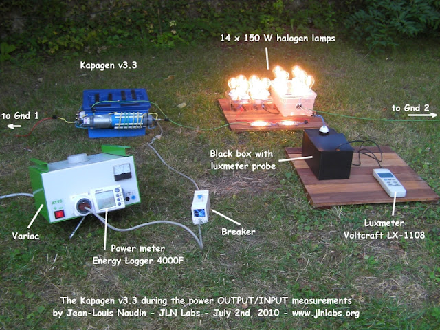
The device is tested here with
Off course any necessary wires, sockets , groundings, box or wooden table etc

The measurements of the input-output power by J-L. Naudin are here

The measurements of the relation of luminosity of the lamps with the power is here

Other things that must me taken care, according to 10-15 other friends who reproduced versions 3.2,, 3.3 or earlier versions are
1) Monitor the temperature of the various parts,like input transformer MOT, diode, and lamps, and substitute them with different specifications to keep them cool
2) Be sure to have the spark gap silent
3) Close all house appliances like TV, radio etc to prevent them from being burned.
4) Some suggest high resistance test charges instead of lamps.
5) Be sure to have the grounding with watered soil so as to make it more efficient.
A video
http://www.youtube.com/watch?feature=player_embedded&v=aOvuQweJsV8
Overall photo of the power and luminocity measurements
Here are some reports of other people that have replicated the device. Notice that some of them, have replicated the earlier versions , which had a third coil on the tube.
(To see all these reports together with their photos go to the link
http://jnaudin.free.fr/kapagen/replications.htm#15 )
More videos and constructors of Kapanadze
http://www.youtube.com/watch?v=B6hVasVR7A
http://pesn.com/2013/04/13/9602295_Demos_by_Fabrice-Andre_Refuge7/
http://www.youtube.com/watch?v=hQVfW1yUqTo
Here are more videos also outside the instructions of the J-L Naudin laboratory.
http://www.youtube.com/watch?v=Z-QvHSyHOuQ
http://www.youtube.com/watch?v=atlnVNy0IDE
http://www.youtube.com/watch?v=atlnVNy0IDE&feature=related

The device is tested here with
14 halogen lamps 150 watts 220 volts.
(with surge arrestors each lamp EPCOS 230 volts, to protect them from burning their tungsten filaments)
Here is a diagram of the output

Here is a diagram of the output

Here is the the list of the parts mentioned above
Central Circuit
The double coil
The diode HV 05-12 F04 (Later constructors have experimented with different diodes, so that the diode remains cool)
The spark gap ( air gap 0.9 mm) (Both rods of the spark gap from tungsten. Later constructors have put the one rod of the spark gap from copper and the other from carbon, which makes the spark gap silent during discharges, and reduces input power by 55 watts)
The capacitor HV 1μF 2000V AC
The resistance 10 M Ohms Internal (1 W )
In the above circuit circulates about 2000 Volts AC.
It seems, according to a video below, that the frequency of the circuit is at the range of
1-1.2 MHerz
1-1.2 MHerz
The Double coil
A PVC tube (Cylinder) for the coils, of diameter 5 cm , length 32 cm
2 sockets at the two circular ends of the tube to connect the wires from the rest of the circuit.
The tube has a long coil on its surface of 108 turns, that occupies about 23 cm length of the tube. The wire for this coil is not more than 30 m, 1.5 square mm (mm^2) cross-section, insulated.
It has also a short coil of only 6 turns, of 2.5 square mm (mm^2) insulated wire.
The short coil of 6 turns is kept in a small distance (not in contact) from the long coil of the many turns, as in the pictures, by plastic rods or tubes and glue.
The coils are of air core.
Inside the PVC tube of the coils, there is a copper tube of diameter 12 mm, and length 40 cm , and inside it a copper rod of diameter 8 mm, and length 40 cm. Both are electrically connected, but it seems better if they are also firmly fitted between them. These two are grounded according to the circuit diagram.
My impression is that as the current is propagating in the long-fine and short-coarse coil, the turning orientation is both counterclockwise or both clockwise, but when putting the two coils geometrically on the cylinder, it would be of opposite turning orientation. Similarly for three coils as in the earlier versions, along the current path, my impression is that it is clockwise (22 turns)/counterclockwise (84 turns) /counterclockwise (6 turns). The next video
http://www.youtube.com/watch?v=hQVfW1yUqTo shows also
that the third grounding of the lamps is connected in between the 84 turns coil and 6 turns coil, something that J.L. Naudin does not have in his circuit-diagram. (http://img600.imageshack.us/img600/1791/imageknr.jpg)
http://www.youtube.com/watch?v=hQVfW1yUqTo shows also
that the third grounding of the lamps is connected in between the 84 turns coil and 6 turns coil, something that J.L. Naudin does not have in his circuit-diagram. (http://img600.imageshack.us/img600/1791/imageknr.jpg)
The input power
A microwave oven transformer of 800 watts.
DCP-M Y 5591 MX Class 200
2400 volts 1710 VA 3.28 V AC (the 3.28 v coil is not used)
The input current is 220 volts AC, 50 Hz
The output is AC 2000 volts
The output charge
5 halogen lamps 150 watts 220 volts.
(with surge arrestors each lamp EPCOS 230 volts, to protect them from burning thei tungsten filaments)
In the current versionof the device, the 2,000 volts output, is send to the halogen lamps. But if we want to send the output to ordinary devices, then we must use an additional transformer to step down the 2,000 volts to 220 volts of an ordinary home appliance.
In the current versionof the device, the 2,000 volts output, is send to the halogen lamps. But if we want to send the output to ordinary devices, then we must use an additional transformer to step down the 2,000 volts to 220 volts of an ordinary home appliance.
The list parts as mentioned by J.L Naudin is

The measurements of the input-output power by J-L. Naudin are here

The measurements of the relation of luminosity of the lamps with the power is here

Other things that must me taken care, according to 10-15 other friends who reproduced versions 3.2,, 3.3 or earlier versions are
1) Monitor the temperature of the various parts,like input transformer MOT, diode, and lamps, and substitute them with different specifications to keep them cool
2) Be sure to have the spark gap silent
3) Close all house appliances like TV, radio etc to prevent them from being burned.
4) Some suggest high resistance test charges instead of lamps.
5) Be sure to have the grounding with watered soil so as to make it more efficient.
A video
http://www.youtube.com/watch?feature=player_embedded&v=aOvuQweJsV8
Overall photo of the power and luminocity measurements

What the say other people that have constructed replications and variations around the world.
Here are some reports of other people that have replicated the device. Notice that some of them, have replicated the earlier versions , which had a third coil on the tube.
(To see all these reports together with their photos go to the link
http://jnaudin.free.fr/kapagen/replications.htm#15 )
# 1 - June 9, 2010 - Kapagen replication by dragon
I've made several attempts with different coils and this is one of the better ones. The whole thing is Tesla basics as you can see in the diagram of the circuit. The picture's show it running a small 40 watt bulb at around 7 watts of input, the variac is set at around 50 volts. The NST is a 120V input with a 6500 volt .02 amp output. I have 2 earth grounds on this one but the second doesn't seem to add anything and can be removed without changing the light intensity or input requirement. One is required.
I've found by playing with various coils and bulbs it's not so much the wattage of the bulb in as much as the resistance of the bulb or bulbs. I have no real way of measuring the output at a wattage level, no claims are being made.... just an interesting experiment.
I've found by playing with various coils and bulbs it's not so much the wattage of the bulb in as much as the resistance of the bulb or bulbs. I have no real way of measuring the output at a wattage level, no claims are being made.... just an interesting experiment.
# 2 - June 9, 2010 - Kapagen successful replication v1.0 by romerouk
I am using 260w in the system and output is at least 500w.The bulbs are more than fully powered. After few more attempts I have destroyed 2 of them. I will have to get some more bulbs tommorow and see how many I can connect and still keep full brightness.I tryed to measure voltage across one bulb and it shows 335v-ac but all my meters are digital and I am sure it is not right.I need to get some analogic multimeters to find the amps and volts at the output.Few minutes ago I have started the system using DC to power the system an now I can see that DC is the only way to keep the system running for longer period of time.Using ac the spark gap becomes very hot as with dc it is much better.Also having a capacitor 90.02mf) connected in parallel with the load, keeps the flickering under control. I hope the picture attached will make all understand the basic of it.
# 3 - June 10, 2010 - Kapagen replication v1.1 and 1.2 by romerouk
I have posted another 2 video-clips testing circuit with high voltage AC then using DC as power source.
...
I am in UK, using 240vac. Every bulb is 100w and I have connected 9x100w. Sorry I forgot to show that in the video... I will do it next time.
I get around 1.6amp using AC to power the system but when I use DC it drops to around 1.15.
...
tube = 5.5cm/140cm - wire 4mm stranded except the big coil = 10mm stranded MOT I have no information about it. the tube is PVC 5mm thick
...
I am in UK, using 240vac. Every bulb is 100w and I have connected 9x100w. Sorry I forgot to show that in the video... I will do it next time.
I get around 1.6amp using AC to power the system but when I use DC it drops to around 1.15.
...
tube = 5.5cm/140cm - wire 4mm stranded except the big coil = 10mm stranded MOT I have no information about it. the tube is PVC 5mm thick
One thing I found is that you need both earth connections directly to the ground and about 10m distance. I didn't try longer distance as I don't have more lenght in the garden.In my first attempt I had one earth was comming from the water supply and the other one from a copper pipe I fixed in the ground.That showed me 2.3 amps for 500w load, then I have fixed another copper pipe in the ground at 10 m distance and I got about 1.6a for 900w load.MOT stays just a little bit warm in my case, maybe you have a defective MOT,run it without anything connected to see if it still gets hot, check capacitor value, if it is too high might create the problems you have.Not recommended to start the device inside the house as it will interfere with all electrical equipment, it does in my case, I have almost destroyed the tv, running the device in the garden.It is a lot of radio waves generated by the device and this is another problem at the moment.Turn off all electrical appliances in the house while testing.
Kapanadze replication v1.1 used 1.7A X 240ac = 408 watts input
Kapanadze replication v1.2 used 1.16A X 240ac = 281 watts input
Kapanadze replication v1.2 used 1.16A X 240ac = 281 watts input
# 4 - June 11, 2010 - Kapagen replication by callanan
Not as good as a variac although much smaller. It's a 1200W AC power controller or lamp dimmer. Not very clean or linear on a transformer but at least gives some means of power control. Some is better then none...http://www.jaycar.com.au/productView.asp?ID=AA0346&keywords=controller&form=KEYWORD
I am using two seperate grounds spikes and not the house ground.
I am using two seperate grounds spikes and not the house ground.
# 5 - June 11, 2010 - Kapagen replication by retrod
Here is my first attempt, so don't laugh . I used a large variac on the 120vac input to the MOT (not shown). I had to work in the basement indoors so I used a copper water pipe feed for one ground and an iron floor drain pipe that leads outside & underground for the second. The spark gap is a non resistor sparkplug with a vice grip for a heat sink. The lamp is a 200watt 120 volt. I used the DC circuit with a small HV cap.
First results:
MOT gets very warm and the 20amp mains circuit breaker trips after 15 seconds of operation. Spark gap is electric blue, not violet. Please be careful with this circuit the voltages present are indeed dangerous.
Dave
First results:
MOT gets very warm and the 20amp mains circuit breaker trips after 15 seconds of operation. Spark gap is electric blue, not violet. Please be careful with this circuit the voltages present are indeed dangerous.
Dave
# 6 - June 12, 2010 - Kapagen replication by retrod
Second attempt. After this mornings smoke test I almost gave up. Then there were some encouraging posts and advice. Here is some progress to report. I noticed on my set-up it works much better with high resistance loads. I started with two 40w light bulbs in series and then thought to try fluro tubes. I am up to six tubes in series with the two original 40w lamps. All the fluro tubes were removed from service a year or more ago as dim or non lighting. It reminds me of when many of us were adding LED's in series working with Dr. Stifflers SEC, what fun!
I have no way right now to measure input current. The voltage out of the variac is 90 volts. The spark has become very quiet with this load. I may post a short video on youtube later.
I have no way right now to measure input current. The voltage out of the variac is 90 volts. The spark has become very quiet with this load. I may post a short video on youtube later.
# 7 - June 15, 2010 - Kapagen replication by woopy
Hello romero and all
OK i am almost ready for a first test. I did the coil exactly as Romero that is 84 turns plus 22 turns plus 6 big turns.the coil 1 and 2 have the same stranded wire (blue) and for the big coil (green and yellow) there is 7 strand of plain copper, the center is made with 4 stranded copper and something torsaded for connection to one ground line, plus the main blue wire connection to the spark gap. the mot is rated 700 watts. I will use it directly (without the cap and diode for a first test. What do you think ? Or can i use the MO cap (0.95 micro farad and 2100 volts) and HV diode.?
I will ground it with 2 ground line conducting to 2 galvanised steel bar going 1 meter deep in the ground. and separated about 15 meter. I intend to use a wire with 3 time 1.5 mm2 bounded ,for the ground lines . I intend to begin with a halogen 500 watts what do you think ?
If it works, i will post the pictures of the construction of the coil step by step.
good luck at all
Laurent
# 8 - June 16, 2010 - Kapagen replication by retrod
Some numbers & a video.
MOT is a OBJY2
Input Voltage : 120vac
Input current : Measured at output of variac 4.0 amps avg
Load: Six 200w 120v Lamps
Earth Grounds : First: 200ft iron pipe (water well). Second: 10 ft driven rod, copper clad
Spark Gap : Champion J-14 with neo magnet attached
Air temperature was 68 degrees Fahrenheit
MOT Temp at start 84 F
MOT Temp at end 107 F
Run time approx 4.5 minutes
# 9 - June 16, 2010 - Kapagen replication by woopy
Hi all
the rain stopped shortly , and could not prevent me to have a second test.
Took all precaution as per Stefan and 3,2,1 go
yaouuh it works very fine. The bank directly connected to the grid does simply no light at all, but with the Kapagen it is near full brightness. i have AC current , no cap at all. I did not make any measure but the grid fuse did not even break. another thing i have a radio on at 10 meters from the kapagen and nothing , no grrrrrbbrrkkkkkk, at all in the radio.
OK and the rain comes again
hope that tomorrow it will be better weather to make some measurements.
just for info the bank as a resistance of 400 ohm. when i connect the bank to the grid, my clampmeter shows 130 ma at 230 volts AC just another thing the bank was on and stopped only when i switched off. but when i tried to take the measre of resistance it was impossible. Than i checked the bulb and one was broken. I mean it seems that i probably had the arc in the bulb which make the bulb on even if the tungsten filament is broken. What do you think?
good luck at all
Laurent
# 10 - June 21, 2010 - Kapagen successful replication by Robert
Dear Mr. Naudin,
Good news!
I got 1800W out and the MOT stays cold even the inlet power meter indicates 800W. I think that’s a real sign of OU. I have 2x150W halogen + 18x 100W bulbs (fully bright) and all serial. If I would have more lamps I think they would shine fully too.
I observed that with the 1N5408 diode didn’t work – but with the BY255 it works very well – just they get hot, so I add cooler.
I don’t know way you changed the coil setup but with the coil relation 22 – 84 – 6 its working quite well.
Many thanks and br.
Robert
# 11 - June 23, 2010 - Kapagen successful replication by Juju
Hi Guys!
I made a video of my setup, is my first one!
i putted some lamps of 60w others of 100w, all in series with a fan/ventilator of 100W... i putted the fan in the end of the sequence going to ground, because it haves a capacitor of 230V, i was affraid it can blow up if it takes all the primary voltage! 2 lamps in the video are not lighting well, but i think it was some problem with them!
this thing can feed all type of devices, not only lamps!
and it is not so spooky as at seems, when the adrenaline goes up, the fear fades! spectacular!
my output dont work well with dc, as you can see, dont used any caps!
dont took measurements because my DMM cannot read alternate current, only dc...
# 12 - June 25, 2010 - Kapagen successful replication by TomB-455
Dear Mr Naudin,
I have tried to replicate your coil and it works!
most of the setup is the same as yours, m.o.t. 800 watt, in dc mode. 10x150 wats halo-bulbs fully bright!!
i checkt my variac (but didn't put it on camera) and it was at 165 volts!!!
exept for the 23ccw turns on the entrance of the coil, those whre nessecery to reduce the input current.
the pictures are folowing soon. i did make a video though.. ;)
best regards,
TomB-455
# 15 - July 2nd, 2010 - Kapagen successful replication by don
Hi Mr. Naudin
The best (lowest input power) I could get was 707 Watts lighting 18 x 100 watt light bulbs without using a variac. It used 570 watts to light 9 of the 100 watt light bulbs.
The best (lowest input power) I could get was 707 Watts lighting 18 x 100 watt light bulbs without using a variac. It used 570 watts to light 9 of the 100 watt light bulbs.
I measured my power usage with a Kill-O-Meter connect to Mains over 30 feet away from my device.
When I first turned my Kapagen on it used over 1100 watts and the lights were approximately 50-60% bright. After playing with this for a week I got the power usage down to 707 Watts and the lights were at least 90% bright. I did this comparison by having one 100 watt light bulb connected to Mains sitting next to one of my light bulbs from my Kapagen. I agree it's not scientific but it was good enough for me to tell the difference.
I did find that dimmer switches and amp restrictors used more power then they were worth so I removed my amp restrictor.
But the most important thing I found was that the ground rods/connections/Earth was the biggest factor in lowering my power usage. I replaced my copper tube with construction grade grounding rods, applied water to the ground around my ground rods. In my area there is 6-12" of top soil and then under that it's all sand. Sand doesn't hold water very well.
Using Carbon rod and Copper for the spark gap lowered my input power usage by 55 watts.
More videos and constructors of Kapanadze
http://www.youtube.com/watch?v=B6hVasVR7A
http://pesn.com/2013/04/13/9602295_Demos_by_Fabrice-Andre_Refuge7/
http://www.youtube.com/watch?v=hQVfW1yUqTo
Here are more videos also outside the instructions of the J-L Naudin laboratory.
http://www.youtube.com/watch?v=Z-QvHSyHOuQ
http://www.youtube.com/watch?v=atlnVNy0IDE
http://www.youtube.com/watch?v=RDfLf4jw9gQ&feature=related
http://www.youtube.com/watch?v=5m-88B5zi4A
http://www.youtube.com/watch?v=25wCTwB1jNs&feature=related
http://www.youtube.com/watch?v=_8aAhDuHHJg&feature=related
http://www.youtube.com/watch?v=gErefbcTz-U&feature=related
http://peswiki.com/index.php/Directory:Kapanadze_Free_Energy_Generator
also
http://www.overunityresearch.com/index.php?topic=237.0
http://www.overunity.com/7679/selfrunning-free-energy-devices-up-to-5-kw-from-tariel-kapanadze/msg189076/#msg189076
http://www.youtube.com/watch?v=Goq76CQapyI&feature=related
http://www.youtube.com/watch?v=Z-QvHSyHOuQ&feature=relmfuhttp://www.youtube.com/watch?v=5m-88B5zi4A
http://www.youtube.com/watch?v=25wCTwB1jNs&feature=related
http://www.youtube.com/watch?v=_8aAhDuHHJg&feature=related
http://www.youtube.com/watch?v=gErefbcTz-U&feature=related
http://peswiki.com/index.php/Directory:Kapanadze_Free_Energy_Generator
also
http://www.overunityresearch.com/index.php?topic=237.0
http://www.overunity.com/7679/selfrunning-free-energy-devices-up-to-5-kw-from-tariel-kapanadze/msg189076/#msg189076
http://www.youtube.com/watch?v=Goq76CQapyI&feature=related
http://www.youtube.com/watch?v=atlnVNy0IDE&feature=related